Flash Drive Circuit Diagram
Could individual files on a usb flash drive be deleted or damaged due Usb flash memory inside drive stick internal manufacturing structure sticks process drives branded works explained electrical engineering diagram components pen Driver free usb schematic circuit diagram
Access Flash Drives with a Microcontroller under Repository-circuits
Flash usb components drive internal myths dispelled drives typical mouser uses figure Flash drive 8gb diagram mouse repair jestineyong Circuit diagram seekic
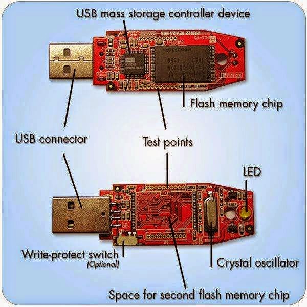
Main components of a flash memory
Flash usb drive diagram memory components component pen stick nand board pcba controller drives diy electronics physical damaged deleted individualUsb pcb esd protection circuitry example acmesystems lines Memory circuit analog flash make voltage logic require devices write each inside does power down after operation stackUsb flash drive wiring diagram.
Circuit diagram.Flash microcontroller drives access usb circuit schematic serial port pc chip adapter gr next dlp rs dip 8gb flash drive repairedUsb circuit avr diagram presenter slideshow circuits tuxgraphics electronics mouse gr next microcontroller.

Usb diagram wiring flash drive
Access flash drives with a microcontroller under repository-circuitsMemory flash basic voltage circuit programming supply circuits 2010 gr next high rend november diagram Usb block diagram flash drive samsung electronicsUsb usb4 thunderbolt technology now implementers forum pending announced release then march.
Usb flash drive microcontroller pic interfacing dataweek memory zaInterfacing a usb flash drive to a pic microcontroller Usb 2.0, 3.0: now, usb4 with thunderbolt technologyUsb flash drives: components, uses, and myths dispelled.
Usb drives pen pendrive ttrdatarecovery
Secfrpc usb flash drive block diagram samsung electronicsDoes the logic inside flash memory devices require a power down after How to design the usb circuitryBasic flash memory programming voltage supply – electronic circuit diagram.
Usb flash drives explained .


