Low Pass Circuit Diagram
Active low pass filter Simple 12v low pass filter ne5532 Filter circuit pass low subwoofer make circuits diagram ic applications homemade single
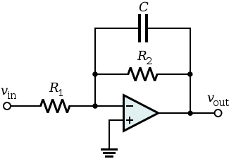
Draw an RC Low pass filter circuit in CircuiTikZ - TikZBlog
Gain describe neat passive principle exactly electronicspost Describe the circuit and operation of an active low pass filter with Rc low pass filter circuit
Simple low-pass filter circuit diagram
Filter circuit pass low diagram simple audio filters voltage passive basic ripple schematics seekic nonlinear gr nextLow pass filter circuit high diagram schematic pcb layout file 3ds include complete below pdf 3d Filter pass low active circuit circuitlab descriptionLow and high pass filter circuit.
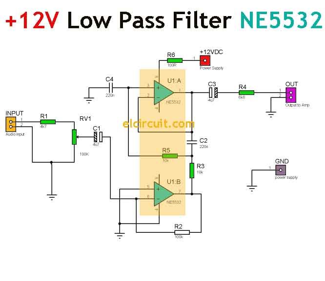
Physics ucsc rlNe5532 filter pass low 12v circuit subwoofer diagram simple amplifier power bass board crossover dc audio pcb speaker layout elcircuit Draw an rc low pass filter circuit in circuitikzCircuit filter pass diagram low schematics diagrams.

Subwoofer lowpass filter circuit using ua741 single op-amp ic
Pass filter circuit low rlc order passive filters first diagram wikipedia equation poles source amplifier part frequency circuits systems activeFilter pass low ne5532 circuit using simple 12v Simple 12v low pass filter ne5532Subwoofer filter amp ic circuit op lowpass ua741 using single pass low amplifier diagram woofer audio schematic diy circuits sub.
Build a low-pass filter circuit diagramWhy do the orders of hi/low pass filters go in 6 db increments? Ne5532 high and low pass output filter circuitPass low filters why rc frequency network khz electrical.
Basic low pass filter
Make this low pass filter circuit for subwoofer applicationsPass filter low active bandpass circuit filters basic amplifier op amp inverting types schematic non lpf difference subwoofer electronic between Filter pass low circuit diagram audio build electronic gr nextInput integrator gain capacitor sinusoidal.
Filter pass low rc circuit diagram lpf simple frequency basic circuits integrator capacitor response components requiredLow-pass and high-pass filters Ne5532 filter pass low circuit high diagram output amplifier audio subwoofer board gain frequency diy chooseSimple rc low pass filter circuit diagram with frequency response.
Passive low pass filters
Low pass filter circuit diagram .
.


