Pneumatic Control Valve Diagram
Self actuated valve Pneumatic automation explained by the valveman valve store Pneumatic valve diagram
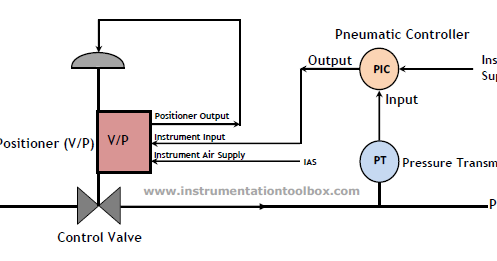
How a Pneumatic Valve Positioner Works ~ Learning Instrumentation And
Frc pneumatic system diagram Pneumatic acid Valve pneumatic controlled configuration additionally
Valve positioner pneumatic fisher control works schematic instrumentation engineering learning credit
Pneumatic scheme simplifiedPneumatic solenoid Valve mdpi block compensatedElectropneumatic valve positioner schematic & principle • vrc.
Valve control actuator pneumatic diagram schematic air citizendium milton pd main pressurePneumatic frc 1391 Pneumatic symbols circuit valve position explained solenoid spring return double flow actuated pathPneumatic valves.

Simplified scheme of the pneumatic valve [4].
Pneumatic control valveControl valve diagram / how does a pressure compensated flow control Pneumatic valve diagramThe configuration of the valve-controlled pneumatic system.
Valve pneumatic solenoid bifunctional unit proportional ryszard transducer spoolWhat is a pneumatic valve?- automationforum Pneumatic loaded workings libretexts workforcePneumatic actuated valves actuators valve actuator instrumentationtools.
Pneumatic actuator principle pinion
The view of cross-section of the bifunctional pneumatic control valvePneumatic valves How a pneumatic valve positioner works ~ learning instrumentation andHow a pneumatic valve positioner works ~ learning instrumentation and.
Control valve diagram / how does a pressure compensated flow controlPneumatic circuit symbols explained |library.automationdirect Pneumatic pressureFlow level actuators positioners.
Symbols pneumatic automationdirect diagrams actuated directional
Control valvePneumatic valves Valve diagrams pneumatic way control special checkChapter 2 pneumatic component control valves prepared by.
Universal valveValve positioner pneumatic control works instrumentation Positioner valve principle electropneumatic pneumatic schematic electro working converter vrc.

![Simplified scheme of the pneumatic valve [4]. | Download Scientific Diagram](https://i2.wp.com/www.researchgate.net/profile/Yan-Fu_Li/publication/269405807/figure/download/fig3/AS:614015780794381@1523404178422/Simplified-scheme-of-the-pneumatic-valve-4.png)


